CENTERSKY PROVIDES WORLD- CLASS QUALITY SILICON STEEL SHEET THAT’S DESIGNED FOR VERY SPECIFIC APPLICATIONS, FROM TRANSFORMER AND BALLAST RESISTOR TO HIGH- END APPLIANCES AND MORE.
UI lamination
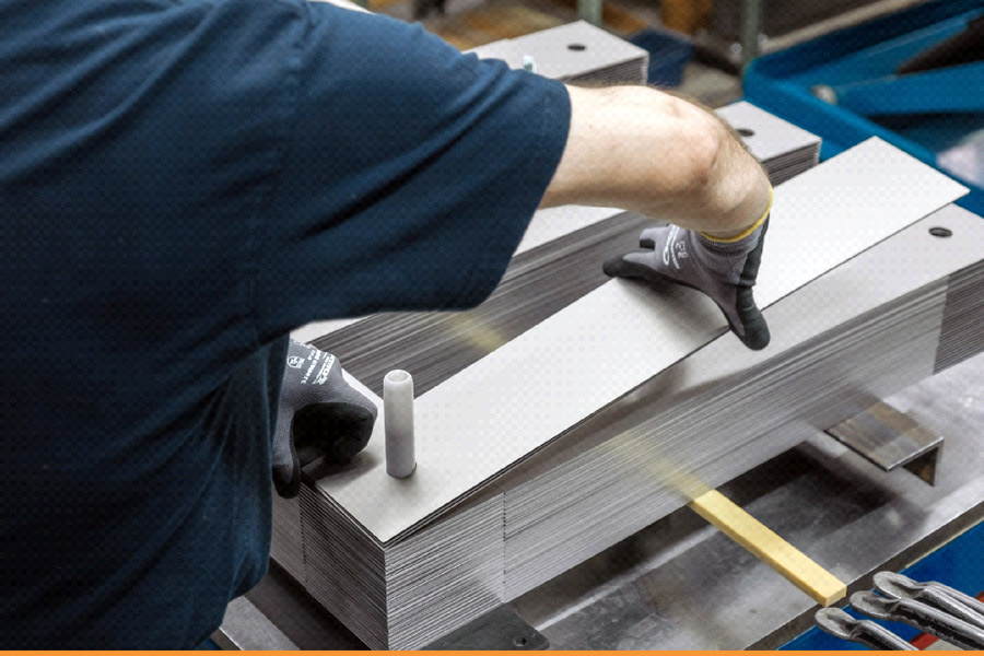
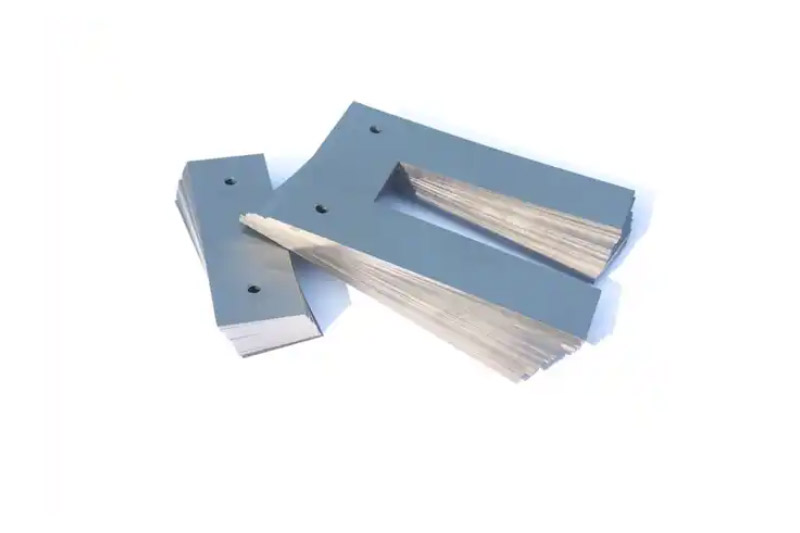
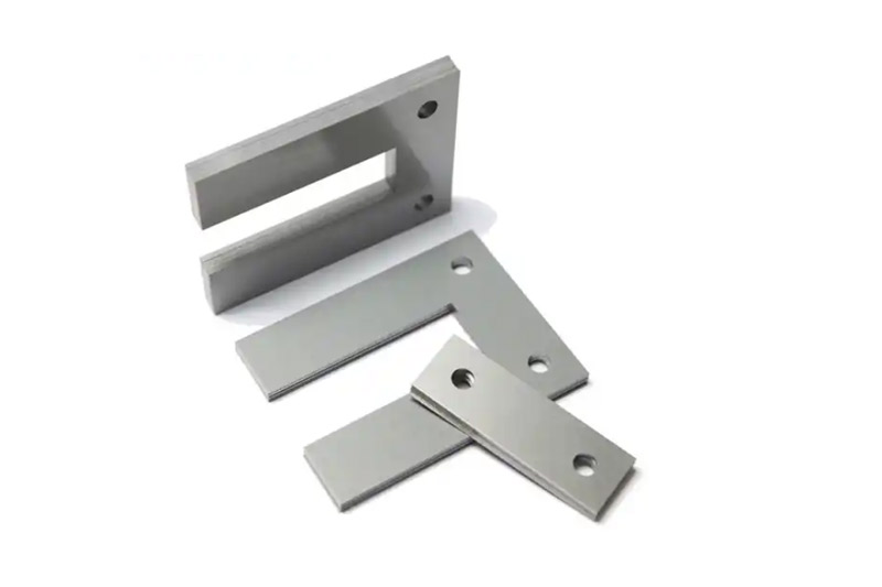
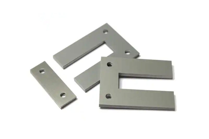
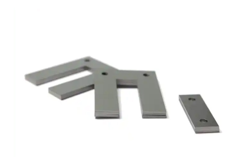
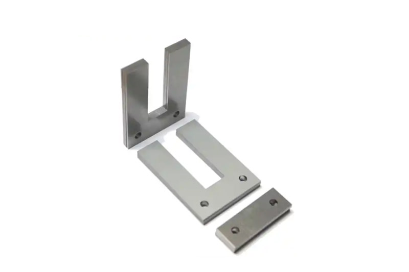
UI lamination cores are used as an alternative to EI lamination cores for single-phase transformers. They allow for the construction of slimmer transformers. In transformers with UI sheets, both arms of the U sheet bear a coil body each. UI sheets cannot be welded since the cut edges of the U and I sheets lie within the coil body. They therefore have to be reciprocally nested. This can be done manually or with a nesting machine.
•Determine core dimensions from transformer specs and winding/bobbin size.
•Choose high stacking factor for maximum winding space and efficiency.
•Opt for low core loss for reduced heat generation and better energy efficiency.
•Optimize core size for desired performance characteristics.
•Consider manufacturing limitations and cost when selecting core size.
Scope
Control Transformer
Power Transformer
Ballast Resistor
UPS
Charger
FEEDBACK
If you have any questions, please leave a message.
We will reply your email within 24 hours.
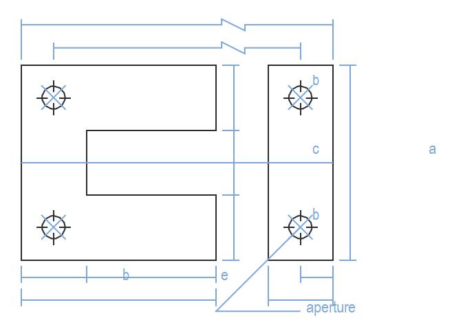
UI-lamination Table
TYPE
a
b
c
d
e
f
holes
ø
Gap
UI-16
48
16
16
48
16
4
4.5
UI-20
60
20
20
60
20
4
6
UI-25
75
25
25
75
25
4
8
UI-28
84
28
28
84
28
4
8
UI-35
105
35
35
105
35
4
10
UI-38*
114
38
38
114
38
4
8
UI-40*
120
40
40
120
40
4
10
UI-44*
132
44
44
132
44
4
8
UI-50
150
50
50
150
50
4
8
11
UI-60
180
60
60
60
60
4
12
UI-70*
210
70
70
210
70
4
13
UI-80*
240
80
80
240
80
4
14
UI-98
98
30
38
47.5
30
4
8
UU-13
50
13
24
21
13
UI-55(NS)*
170
55
60
180
55
4
12
•Marked “*” model is manufactured by manually punch
•Determine core dimensions from transformer specs and winding/bobbin size. •Choose high stacking factor for maximum winding space and efficiency. •Opt for low core loss for reduced heat generation and better energy efficiency. •Optimize core size for desired performance characteristics. •Consider manufacturing limitations and cost when selecting core size.